Charging or Discharging in RC circuit
circuit description
Overview
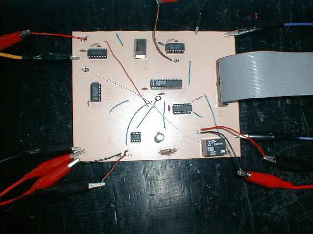
A capacitor is charged or discharged thru a resistor by a relay operation, and its voltage is continuously monitored by AD converter at every SAMPLE signal generated by a function generator. Time variation of analog input voltage is very slow, so no S/H circuit is used, which greatly simplifies this circuit. When each AD conversion is completed, converted voltage is transmitted to PC through 12-bit interfacing. The results are processed by C-language program and volt-time graph is displayed. This graph will be fitted to extract the time constant RC. Time constant can also be found from the graph itself.
Operation
This circuit can be operated either in CHARGING mode or in DISCHARGING mode. At first, sampling frequency should be entered.
(1) When CHARGING mode is selected, relay is initially set to NC position and capacitor is completely discharged.
(2) When DISCHARGING mode is selected, relay is initially set to NO position and capacitor is fully charged.
(3) Once the charging or discharging process commences, capacitor voltage is digitalized by ADC at every SAMPLE signal. At the end of each conversion, FLAG is set.
(4) PC checks this FLAG at every instant. When FLAG setting is detected, PC performs both counter-reading and FLAG-resetting simultaneously.
Circuit diagram
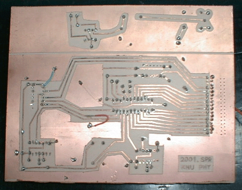
circuit photos


measured data
R=33 kilo-ohm C=22 micro-farad
sampling frequency = 100 Hz


