Air Tube Resonance and the Speed of Sound Wave
circuit descriptions
Overview
Air tube resonance experiment system was developed using several discrete circuit elements, PC interfacing, and some materials that can frequently be found around us. Experiments were preceded in two different ways, the one is in tube length scanning, and the other is in frequency scanning. In both experiments, acoustic wave was continuously detected by a microphone and amplified. Then, intensity level of the sound could be obtained by feeding the amplified signal to the envelope detecting circuit. The signal data was quantized by the analog-to-digital converter and finally is collected by PC through interfacing circuit. The instrument developed in the present study displays the intensity of wave as a numerical quantity and enables to visualize the invisible sound wave resonance phenomena, which will promote the interest on scientific experiment of the students.
Operation
This circuit can be operated either in TUBE LENGTH SCANNING mode or in FREQUENCY SCANNING mode.
(1) When TUBE LENGTH SCANNING mode is selected, the amplitude of detected wave is continuously checked with the tube being filled up by water.
(2) When FREQUENCY SCANNING mode is selected, the level of water in the tube is fixed. Instead, the intensity of detected wave is checked with the frequency of Audio Generator being varied.
(3) Once the measuring process begins, the amplitude of the wave is converted to a digital code by ADC at every START signal. At the end of each conversion, EOC is activated and this is checked by PC. At the same time, SAMPLE/HOLD latches next analog signal. (This will be released by the next START signal.)
(4) PC checks this EOC at every instant. When the EOC setting is detected, PC performs both code-reading and next measuring process simultaneously.
circuit diagram
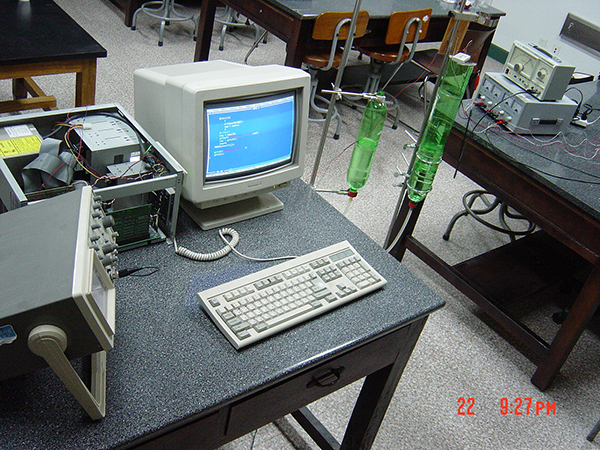
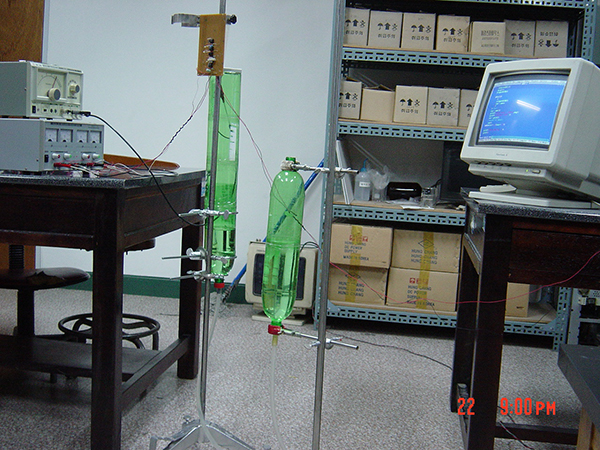
circuit photos